
FILTER SPECIFICATIONS I
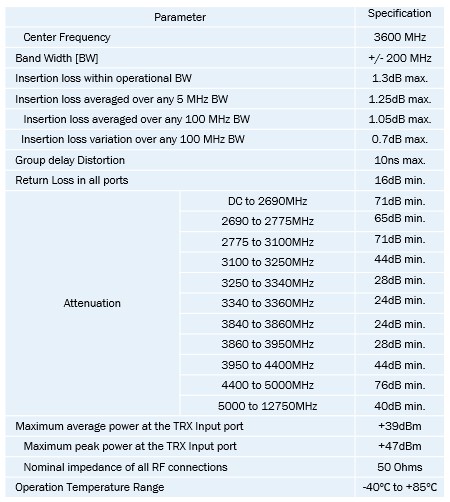
- The preliminary specifications as supplied by the vendor are given on the right-hand side.
- The filter is expected to operate at a centre frequency of 3.6 GHz with a maximum insertion loss of 1.3 dB at pass-band edges.
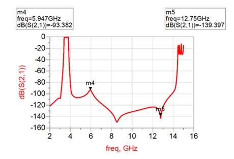
- The filter needs to be free of spurious emissions up to 12.75 GHz. The spurios response can be taken care of by the addition of a low-pass filter, however, that will come at the expense of additional insertion loss.
- Passband specs can be meet both with standard ceramics supplied by the vendor and with our standard distributed resonator solutions, however, out-of-band specs are more difficult to achieve. Here, standard TEM solutions have the first spurious response at 3 times the fundamental frequency, standard waveguide ceramics at less that 2 times, with our standard distributed resonator approach being in the similar range.
- Here we present approach that combines the vendor’s strength in ceramics combined with a resonator design to provide a wide range spurious response.
FILTER SPECIFICATIONS II
- The passband filter specifications can be met with a resonator of an unloaded Q-factor of about 1,300. The entire filter needs to fit into an envelope of 92.5 x 20.5 x 6 mm3 including connectors. If space allocated to the connectors is excluded, the total space available to the filter is 82.5 x 20.5 x 6 mm3.
- The topology of the filter has to be chosen in accordance to meeting the filter specifications, but also bearing in mind the manufacturing ease.
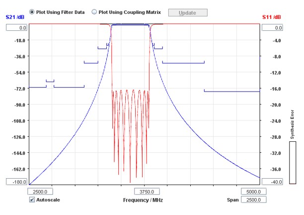
- For example, the passband specs can be achieved using an-inline coupled filter of the 9th order (9 resonators with easy fabrication) or with cross-coupled 8th order (8 resonators). The required cross-coupling for the 8th pole filter makes fabrication difficult.
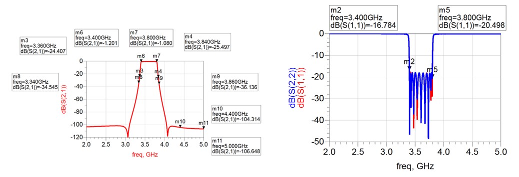
- The passband response of the 9th order inline filter is shown on the right hand side.
3.6 GHZ RESONATOR PERFORMANCE – MINI COAX LOADED WITH CERAMIC
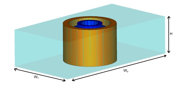
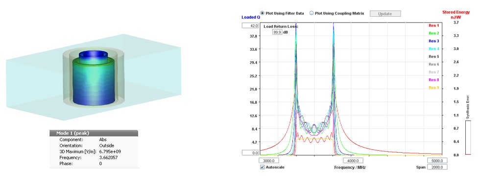
- The ceramic (Kyocera εr = 20 with tan(δ) = 2e-5) loaded mini coaxial resonator internally developed is unable to reach the desired unloaded Q-factor of over 1,400 in an internal volume of 17.3 x 9 x 4.9 mm3 at 3.6 GHz.
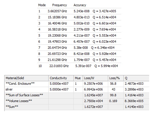
- The resonator with these dimensions is shown on bottom of the slide, while the Eigenmode analysis for the first 10 modes is shown on the table opposite.
- The standard resonator has the first spurious response at 15 GHz which is approximately 4.1 times greater than the fundamental frequency.
3.6 GHZ FILTER PERFORMANCE – INPUT COUPLING
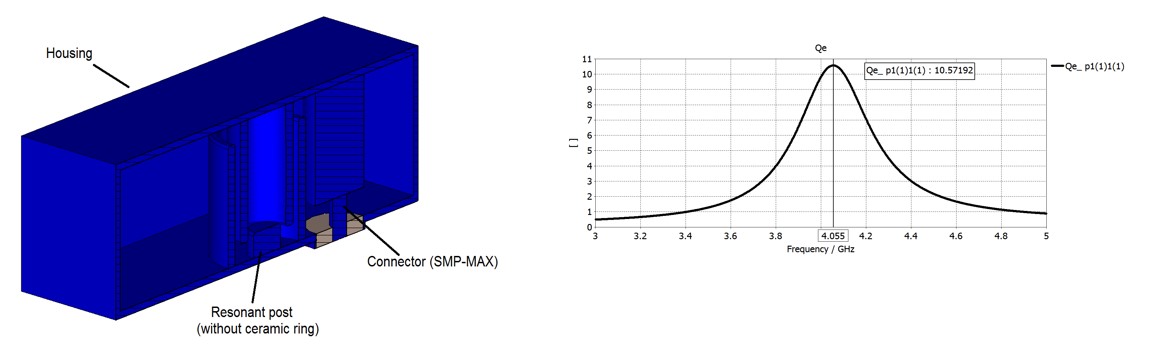
- Due to heavy loading (percentage bandwidth of 11.1 %), the ceramic ring is removed. This results in no or only a very mild influence on performance
- The connector is SMP-MAX.
- The proximity to the resonator determines coupling bandwidth and filter performance
3.6 GHZ FILTER PERFORMANCE – MAIN FILTER – I
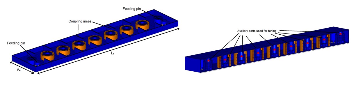
- Discrete ports used for tuning in a circuit simulator
- Silver conductivity in full-wave simulations reduced by 20 % to take into account possible manufacturing imperfections
3.6 GHZ FILTER PERFORMANCE – MAIN FILTER – II
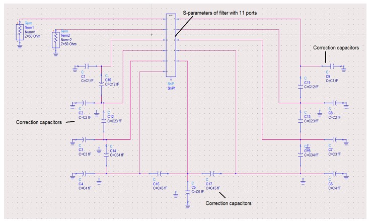
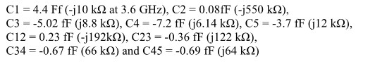
- Discrete ports used for tuning in a circuit simulator
3.6 GHZ FILTER PERFORMANCE – MAIN FILTER – III
- Meets specs
- Silver conductivity in full-wave simulations reduced by 20 % to take into account possible manufacturing imperfections
3.6 GHZ FILTER PERFORMANCE – MAIN FILTER – IV
- Meets and exceeds specs
- Silver conductivity in full-wave simulations reduced by 20 % to take into account possible manufacturing imperfections
3.6 GHZ FILTER PERFORMANCE – MAIN FILTER – V
- Maximum power handling 47 dBm.
- In reality will be higher, due to the presence of ceramic
3.6 GHZ FILTER PERFORMANCE – MAIN FILTER – VI
- Main contributor to performance degradation of the filter as function of temperature is thermal expansion of resonators, in particular, their length.
- The nominal length of resonators is:
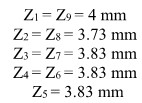
- Under the assumption of the resonators made out of aluminium (CTE = 22.2X 10^6 ), the percentage change in length for a change from 20 C to 80 C is + 0.125 %, while the change in length for temperature change from 20 to -40 is 0.15 %.
- Under the assumption of the resonators made out of invat (CTE = 1.5X 10^6 ), the percentage change in length for a change from 20 C to 80 C is + 0.00975 %, while the change in length for temperature change from 20 to -40 is 0.009 %.
- The small change in the length using invar is not expected to influence the performance of the filter for changes in the temperature
Leave a Reply