Continuously growing demands for higher speeds and higher throughputs places a strain on the existing technologies and, at the same time, calls for new technical solutions with a higher capacity and efficiencyof wireless communications. High throughputs are achievable using three sets of means:
- Bandwidth increase.
- Increased spectral efficiency.
- Spatial reuse, antenna arrays, MIMO.
In standardized wireless communications systems, bandwidths cannot be increased arbitrarily, as they are strictly controlled by standardization bodies, such as 3GPP [1]. As such, option 1 is of limited immediate influence and needs to be viewed both holistically and in the context of adequate standards.
Option 2 appears interesting and has been used to increase data rates, through the introduction of high order modulation schemes. The increase in the data rates that can be “compressed” using high order modulation schemes is, unfortunately, followed by sensitivity increase, resulting in data loss and reduced physical range at which high data rates are achievable. Ultimately, the increase in spectral efficiency has to be supported by high-performance Radio Frequency (RF) components.
Option 3 has gained widespread interest in recent years, as a reliable means to increase data throughput and is the main topic of the present article. By abandoning the single antenna (omnidirectional) concept and introducing antenna arrays [2], the concept of beamforming is born. In simple terms, beamforming
antenna array (d)
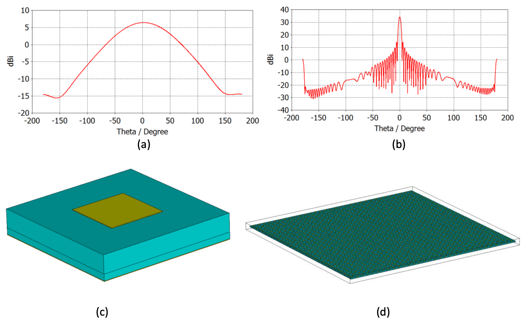
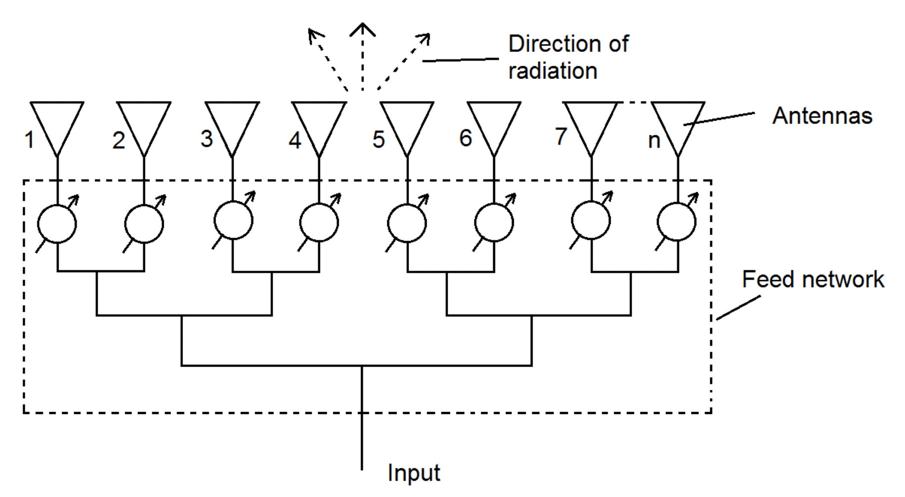
relies on the use of several antennas, fed with signals of appropriate amplitudes and phase such that the composite signal at a particular angle exhibits constructive inference, while at all other angles it experiences destructive interference. Even though the concept of antenna arrays is old [3], it has only recently been employed in commercial telecommunications, such as 5G. Fig. 1 (a) shows the radiation characteristics of a single patch antenna (Fig. 1 (c)) operating at 11.7 GHz with a gain of 6.4 dBi. The angular width or 3 dB bandwidth of this antenna is about 90o, which is standard for this antenna type. The radiation characteristics of the antenna array consisting of 32×32 (1024) antenna elements, identical to those in Fig. 1 (c) in the direction perpendicular to the array is shown in Fig. 1 (b). As one can see from here, the gain of the array is around 34.4 dBi, with an angular bandwidth of only 3.6o. This is a tremendous increase of power being radiated towards a desired used, compared to the case of the single antenna. On the linear scale, this corresponds to the power increase of over 600 times! Also, of note is the existence of many transmission zeroes in the response of the array, which is a direct consequence of destructive interference. This is of particular use to block communications to undesired users. Fig. 1 (b) shows the radiation characteristics for the case when both the azimuthal and elevation angles are equal to zero. This case occurs when the signals feed each antenna element are of the same phase. However, antenna arrays can do much more – they can steer the radiated beam, usually between -45o to 45o, in both azimuthal and elevation planes but this is application dependent. Beam steering is accomplished by the addition of a phase shifter behind each antenna element, as shown in Fig. 2.

Examples of the beam being steered to -15o and -45o in the azimuthal plane are shown in Fig. 3. Antenna arrays appear to solve many important communication problems and their advantages can be summarized as:
- Gain increase and, hence, throughput.
- Relatively simple construction – what is required is to bring antenna elements in a close proximity to each other (to avoid grating lobes, antenna spacing should be around half-wavelength at frequency of operation).
However, these antennas are not without drawbacks. Below, some are listed:
- In the case of very large antenna arrays, a great deal power is lost in the distribution network, which usually limits the size of the array.
- The requirement for a phase shifter for beam steering behind each antenna element leads to high implementation costs, as adequate performing phase shifters are expensive.
- Due to their principles of operation based on interference, beam steering beyond -60o and 60o is usually very challenging, due to the appearance of grating lobes.
In order to overcome these drawbacks of antenna arrays, a variety of watered-down solutions have been developed, such as switched beam antennas (Butler matrix), which consists of switches and fixed value phase shifters. Such a solution, even though appropriate for many applications, suffers from the same problem as antenna arrays, such as performance degradation due to grating lobes.
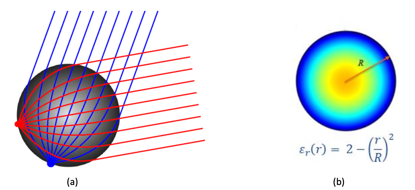
An interesting, but often overlooked solution for beamforming is the Luneburg lens [4]. The traditional Luneburg lens is shown in Fig. 4 and is of a spherical shape. The lens is a natural beamformer as it converts a point EM source into a collimated (plane) wave at a diametrically opposite direction, provided that the sources is placed on its edge, as shown in Fig. 4 (a). The correct operation of the Luneburg lens is achievable provided that the gradient of dielectric permittivity follows the equation given in Fig. 4 (b). In other words, an ideal Luneburg lens has a dielectric permittivity of 2 at its centre and 1 at its edges. This condition can be very easily met in practice by using a variety of fabrication techniques, such as 3D printing [5], however,
other techniques could also be employed. Beam steering with a Luneburg lens can be achieved using a switching matrix connected to several points on the sphere of the lens. Through a selection of appropriate excitation point sources using a switching matrix, a beam can be created in a desired direction. The gain provided by the Luneburg lens is fully dependent on the size of the lens and usually, the bigger the lens, the greater the gain. As an example of the achievable antenna gains, a lens antenna with a diameter of 6𝜆0 provides a gain of almost 16 dBi [5]. An interesting feature of the Luneburg lens is the low-level of sidelobes, compared to standard antenna arrays and scanning angles from, theoretically, -90o to 90o. Usually, in practice, this is reduced to the ground effect to -75o to 75o, but, in general, can be designed for higher scanning angles.
Compared to antenna arrays, the main advantages of the Luneburg lens antenna are:
- Very simple construction.
- Higher power handling capability, due to the use of switches, rather than varactors in phase shifters. Wide scanning angles and low level of sidelobes.
However, they also exhibit some drawbacks, such as:
- Luneburg lens antennas are volumetric antennas, as opposed to antennas arrays, which are of a very low profile. This is usually not a problem at high frequencies but is quite challenging for lower frequencies.
- Integration of the Luneburg lens antenna with Transceiver (TRX) circuitry is more challenging compared to antenna arrays.
Despite these disadvantages, the Luneburg lens antenna is gaining popularity, particularly in the context of mm-wave 5G communications.
In conclusion, beamforming is an attractive way to increase data throughput in communications networks and it can be implemented in several ways. However, choosing the right beamformer is ultimately dependent on the application and great care needs to be exercised prior to realisation.
References:
[1] https://www.3gpp.org/.
[2] S. Yamaguchi, H. Nakamizo, S. Shinjo, K. Tsutsumi, T. Fukasawa and H. Miyashita, “Development of active phased array antenna for high SHF wideband massive MIMO in 5G,” 2017 IEEE International Symposium on Antennas and Propagation & USNC/URSI National Radio Science Meeting, 2017, pp. 1463-1464.
[3] https://en.wikipedia.org/wiki/History_of_smart_antennas.
[4] https://en.wikipedia.org/wiki/Luneburg_lens.
[5] S. Bulja et al., “Millimeter-wave 3D printed Luneburg Lens Antenna”, in IEEE RADIO, Reunion, France, September 2019.

Leave a Reply