
Radio Frequency (RF) filters/diplexers are very important in all types of telecommunications equipment. They help filter out the unwanted frequencies and only let the frequencies that the communication system is designed for to pass through. They are used both in Time Division Duplex (TDD) and Frequency Division Duplex (FDD) systems, however there are some slight differences between them. For example, filters/diplexers in FDD systems usually need to meet stricter electrical requirements compared to their TDD counterparts – this is simply since in FDD systems the transmit (TX) and receive (RX) channels are frequency separated whereas in TDD systems they occupy the same frequency band but operate at interleaved time intervals. As such, in FDD systems, filters/diplexers need to be carefully designed to avoid signal leakage between its TX and RX branches. Usually, the leakage from TX to RX is of greater concern due to much higher powers involved with the TX channel. Such problems do not exist with TDD systems as the entire filter’s/diplexer’s passband is shared between the TX and RX channels.
As frequency bands became crowded with the arrival of 3G and 4G communication technologies, the need for high-performing filters and diplexers, capable of providing adequate frequency separation became even more prominent. Here, such high performing filters/diplexers were not only required to separate neighboring frequency bands, but, at the same limit the amount of insertion losses as losing even a fraction of dB at high transmit powers results in high power losses and creation of heat. This problem was particularly pronounced at the Base Station TX side, due to high powers that needed to be transmitted. As an example, the loss of 1 dB in a base station rated at 50 dBm (100 W), infers a signal loss of 20 W. The situation at the mobile terminal is less demanding since its TX powers are much lower – usually limited to 30 dBm (1W). In this case, the focus is placed on filter/diplexer miniaturization rather than on electrical performance – this is a direct consequence of the fact that it is more forgiving to lose a fraction of power at 1 W, compared to a fraction of power at 100 W.
Given this perspective, choosing a filter/diplexer is highly dependent on the type of the communications system (FDD vs TDD), their location in the system (TX or RX) and whether the filter is to operate within the base station or the mobile terminal. To meet electrical filter/diplexer specifications, the designer has a palette of different filter/diplexer types at their disposal. Examples include cavity filters/diplexers, ceramic filters/diplexers and Printed Circuit Board (PCB) filters/diplexers, to name but a few. Usually, the highest performing filters/diplexers are ceramic based with unloaded Quality (Qu) factors of individual resonators up to 5,000. They are closely followed by silver-plated metal cavity filters/diplexers with individual unloaded resonator Q-factors of up to 3,000-3,500. PCB resonators are among the lowest performing resonators with individual resonator Q-factors rarely exceeding 200-300, however, this is strongly dependent on the losses of the PCB substrate. Traditional 3G, 4G and 5G base stations would almost exclusively make use of cavity filters due to their inherent cost advantages over ceramic filters, while being able to satisfy very stringent performance requirements. In some instances, though, one or several resonators in such a cavity filter/diplexer would be replaced by a ceramic resonator to improve its performance and meet specifications.
In addition to requiring excellent electrical performance, filters/diplexers are also required to operate across a wide temperature range, typically between – 40o C up to + 90o C, with a minimal impact on the insertion losses in the passband and with a maximum insertion loss increase of no more than 10%. Furthermore, in addition to the electrical and thermal specifications, filter specifications additionally stipulate the maximum form factor, i.e. space that the filter/diplexer can occupy. This point is of extreme importance, especially if one considers the fact that standard diplexers in a Remote Radio Head (RRH) operating below 6 GHz occupy up to 70% of its total volume and a great deal of effort is dedicated to its minimization. In the following, we will examine typical 5G FR1 filter characteristics and show how these can be met.
5G FR 1 filter design
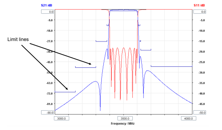
An example of specifications of a typical 5G FR1 [1] base station TX filter with a maximum average RF power handing of 50 dBm are shown in Fig. 1. The return losses are expected to be, usually, lower than -18 dB in the passband.
| Frequency range (MHz) | Filter attenuation (dB) | |
| 0.1 | 3150 | 71 |
| 3150 | 3300 | 50 |
| 3300 | 3380 | 27.5 |
| 3380 | 3390 | 14 |
| 3400 | 3600 | Inband (1.35) |
| 3610 | 3620 | 14 |
| 3620 | 3625 | 27.5 |
| 3625 | 3700 | 35 |
| 3700 | 4200 | 49 |
| 4200 | 4400 | 75 |
| 4400 | 5000 | 81 |
| 5000 | 6800 | 45 |
| 6800 | 7200 | 62 |
| 7200 | 10200 | 35 |
| 10200 | 10800 | 62 |
| 10800 | 12300 | 60 |
| 12300 | 29500 | 30 |
Fig. 1 Typical 5G FR 1 sub 6 GHz filter specifications
As can be seen, the specifications not only stipulate the performance of the bandpass filter in its passband (3.4 GHz – 3.6 GHz) and its vicinity (3 GHz – 4 GHz), but its performance up to 30 GHz. This is done so that the bandpass filter does not interfere with the operation of other communications devices. The response of a bandpass filter capable of satisfying the filter specifications of Fig. 1 in the frequency range from 3 GHz to 4 GHz, can be shown to consist of at least 8 resonators with 4 cross-coupling sections and the individual resonator Qu of at least 2,700, Fig. 2. However, the fact that the specifications extend up to 30 GHz infers the spurious response of the individual resonators that the filter is composed of needs to be considered. Standard coaxial resonators coaxial resonators traditionally offer a spurious-free response up to 3 times the fundamental frequency (3*f0), which would indicate that the proposed bandpass filter would be capable of meeting the specifications up to 10 GHz, but it would fail to meet the remaining specifications of Fig. 1. Ceramic resonators fare much worse, with a spurious-free window being on average between 1.5*f0 and 2*f0 wide. An example of a high-performing resonator with a wide spurious-free window is a mini-coax resonator, offering a spurious free performance over 7 times greater than the
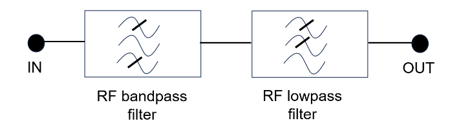
fundamental frequency [2]. However, even with such a wide spurious-free-window resonator, it would be difficult to meet the full specifications as indicated in Fig. 1. In such cases, it is necessary to perform additional filtering – this is usually performed by connecting a wide passband low-pass filter with the designed bandpass filter, Fig. 3. The cut-off frequency of such a low-pass filter is positioned above the passband frequencies of the bandpass filter in order not to induce additional filter losses.
Due to their wideband realization, such lowpass filters have low insertion losses, typically between 0.2 dB to 0.3 dB. However, this commensurately increases the total passband losses of the filter structure obtained in this way, Fig. 3. To be exact, the total insertion loss would now be equal to anywhere between 1.55 dB and 1.65 dB, which does not satisfy the requirements of Fig. 1. To ameliorate the situation, the designed 8-pole bandpass filter needs to be composed of higher Qu resonators so that the combined insertion losses of the filter structure of Fig. 3 are close to 1.35 dB. This is obtained when the Qu of individual resonators is increased to 3,500, which is a significant increase compared to 2,700 as originally calculated. The increase in Qu demands either an increase in the resonator size or use of more expensive technologies.
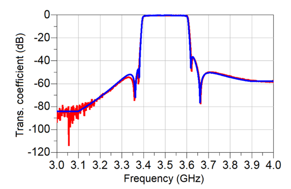
For the physical realization of the proposed bandpass filter, we used an innovative resonator design which makes optimal use of the available volume and requires little or no post-production tuning. The measured Qu of the proposed bandpass filter resonators is around 3,500, which in combination with a lowpass filter with an insertion loss of 0.25 dB satisfies the filter requirements of Fig. 1. The response of the fabricated bandpass filter is shown in Fig. 4. The response of the simulated bandpass filter is also shown.
5G FR 2 filter design
The design of mm-wave filters/diplexers follows a similar path to that of its sub 6 GHz counterparts, however, there is one significant difference. For example, while the electrical and thermal performance of such filters/diplexers is still important, post-production tuning of all, but PCB-based filters has now gained a greater level of importance. To be exact, nearly every high performing filter/diplexer operating in the sub 6 GHz frequency range needs to be manually tuned for correct frequency and bandwidth of operation. This was usually performed using tuning and coupling screws – the interested reader can refer to our earlier article on how to design and tune an RF filter. Since filters and diplexers operating at sub 6 GHz are several times physically larger than filters/diplexers operating at mm-wave frequencies, it was relatively easy to perform tuning using frequency and coupling screws. However, performing manual filter/diplexer tuning of mm-wave filter is a much more difficult task and therefore more costly. To reduce the cost of such devices, filter suppliers usually provide their filters “as is”, with a degree of detuning being acceptable. From the point of view of applications this is acceptable as the 5G mm-wave frequency bands are not as congested as their sub 6 GHz counterparts and a degree of signal spillover can be tolerated. However, as we move towards greater usage of the mm-wave bands, this is expected to become a problem that needs to be addressed in a cost-effective manner, preferably by obviating post-production tuning altogether. One notable filter example which requires no, or little post-production tuning is the distributed resonator concept, [3-5], Fig. 5. Here, the individual resonator consists of a matrix of sub-wavelength resonant elements closely coupled to each other. Because the resonant frequency of operation of the proposed resonator is no longer a function of only one resonant element, but of the spatial arrangement of many such elements, this makes the frequency of operation of the proposed resonator less prone to manufacturing inaccuracies, thus obviating the need for post-
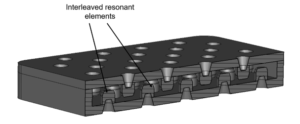
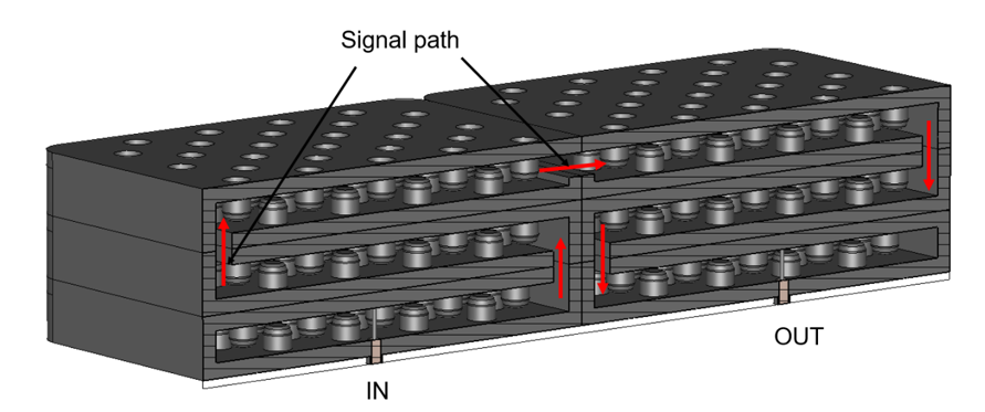
production, which leads to sizeable cost reductions. The authors refer to this feature as dimensional averaging.
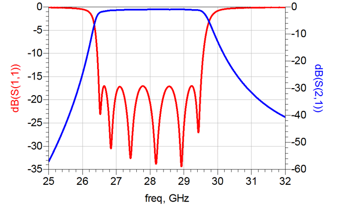
A 6-pole designed filter operating at a centre frequency of 28 GHz with a bandwidth of 3 GHz is shown in Fig. 6 and its response is shown in Fig. 7. The individual resonator has a size of 5 x 5 x 0.4 mm3, corresponding to an electrical height at 28 GHz of only 13o. It unloaded Q is about 500, which is adequate to yield a maximum insertion loss of about 1.5 dB at band edges, with a minimum return loss of -16 dB. The filter requires no post-production tuning and is expected to be fabricated using metal stamping.
Conclusion
In this article a compact overview on important 5G filter and diplexer characteristics is presented. The article presented a real-world example characteristics that typical 5G FR 1 base station filters need to satisfy and presented main issues associated with 5G FR 2 filters and diplexers.
References
[1] https://en.wikipedia.org/wiki/5G_NR_frequency_bands
[2] E. Doumanis, S. Bulja and D. Kozlov, “Compact coaxial filters for BTS applications”, in IEEE Microwave and Wireless Components Letters, vol. 27, issue 12, pp.1077-1079, 2017
[3] S. Bulja and D. Kozlov, “Multi-layered PCB distributed filter”, Electronics Letters, vol. 57, no. 3, February 2021
[4] S. Bulja and D. Kozlov, “Low-profile and low-volume distributed-split resonators and filters”, IEEE Access, vol. 8, Oct. 2020, doi:10.1109/ACCESS.2020.3037666
[5] S. Bulja and M. Gimersky, “Low profile distributed cavity resonators and filters,” in IEEE Trans. Microwave Theory and Tech., vol. 65, issue 10, pp.3769-3779, 2017

Leave a Reply