Phase shifters are omnipresent in telecommunications. They play an important role in radar, phased-array and receiver systems. Reflective-type Phase Shifter (RTPS) circuits, with inherently well-impedance matched inputs/outputs are of particular interest for applications where high phase shift values, excellent performance and small size are of importance.
The amount of obtainable phase from an RTPS is dependent on the structure of its reflective loads, as indicated by the wealth of the literature. The standard RTPS configuration consisting of varactor diodes in the circuits of the reflective loads [1] gives rather modest values of phase shift. These can be increased by resonating the varactor diode with a series mounted inductor [2], however, for phase shifts over 360o at least two varactor diode resonant circuits are necessary [3, 4, 5, 6], typically realized with two series varactor diode-inductor connections mounted in parallel. The parallel connection between the varactor diode and the resonant inductor was mentioned in [7], however, no measured results were presented. As such, it is instructive to studiously examine the performance of the parallel-series configuration and compare it with its series configuration counterpart in the circuit of the reflective load.
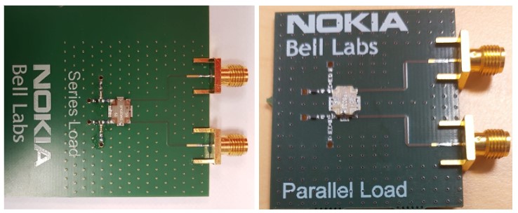
In this paper, we theoretically and experimentally examine the series and parallel resonant circuits in the (RTPS) configuration. Initially, equations are derived to theoretically assess the fundamental limits of both configurations, in terms of the optimum values of the required resonant inductances and, subsequently, the maximum obtainable phase shifts of both configurations, as a function of the reactive parameters of the varactor diode. Then, based on these predictions, two RTPSs operating at a center frequency of 2.3 GHz are designed, simulated, fabricated and their performance was measured and compared with the theoretically predicted results. The measurements indicate that the parallel circuit configuration achieves a variable phase shift up to 288o with a corresponding Figure-of-Merit (FoM) of about 88 deg/dB, while the series resonant circuit exhibits a variation of phase up to 260o with a FoM of about 94 deg/dB.


Leave a Reply