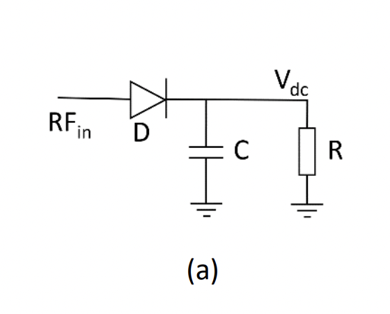
With reference to Fig. 2 (a) in Part I, each parameter influencing the efficiency of a rectifier operating at 10 GHz is examined. As a reminder, its efficiency is examined as a function of a) influence of threshold and breakdown voltages; b) influence of loss; c) influence of diode’s parasitic resistance; d) influence of diode’s junction capacitance; e) influence of termination type and f) influence of package parasitics.
A. Influence of threshold and breakdown voltages on efficiency
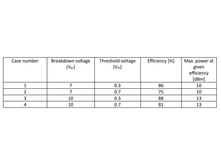
Let us now assume that all components in the circuit of Fig. 2 (a) of Part I are ideal apart from the threshold and breakdown voltage, which assume finite values. Table I below lists the assumed values, efficiencies recorded and the input power level at which the efficiency was recorded. As can be seen, maximum efficiency is obtained for the case when the breakdown voltage is high and when the threshold voltage is low. This is intuitively understandable and points to one way of increasing efficiency in rectifying circuits.
B. Influence of loss
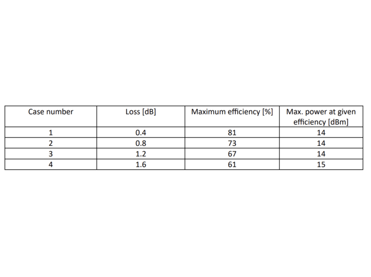
In a similar way compared to A., the influence of loss is also examined. For this purpose, 4 cases are identified, as given in Table II. As can be seen, losses negatively affect the overall efficiency, with efficiency dropping from 81% for 0.4 dB of insertion losses to 61% for 1.6 dB losses. The marginal increase in the maximum poweris explained by the fact that losses reduce the maximum power reaching the active device (diode in this case).
C. Influence of diode’s parasitic resistance
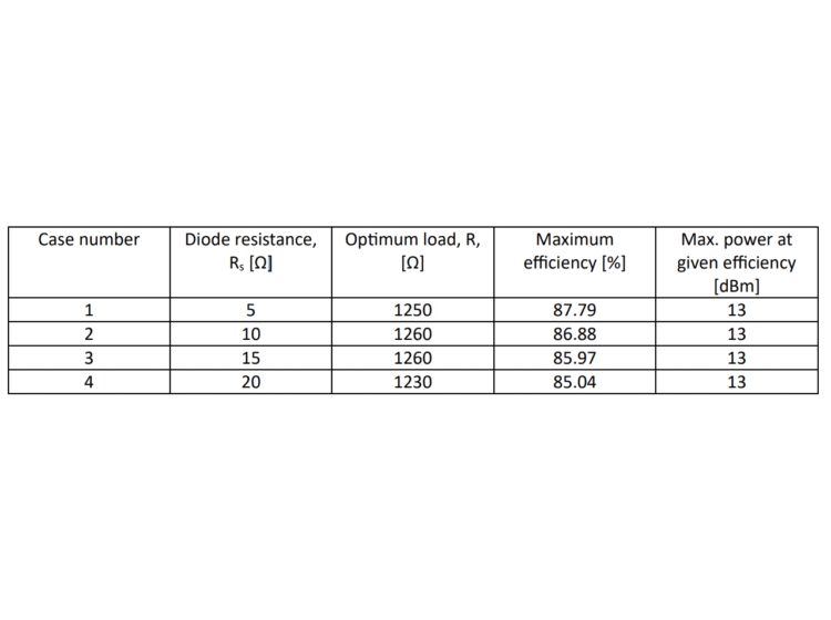
As with the previous two cases, a compiled Table III shows the effect of increase of parasitic resistance. As can be seen, the increase in the diode’s parasitic resistance reduces the overall efficiency of the rectifier, however, the reduction in the efficiency is not as dramatic as it was for case B, investigated previously.
D. Influence of diode’s junction capacitance
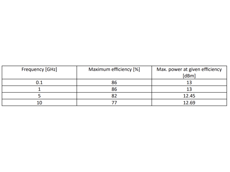
Here, the influence of diode’s junction capacitance is investigated for frequencies up to 10 GHz. For the purpose of this exercise, it was assumed that the diode’s series resistance is Rs = 10 Ω and storage time TT = 10 ps. The diode’s zero voltage junction capacitance is assumed to be Cj0 = 0.2 pF. Table IV shows the effect of the finite capacitance on the overall efficiency as function of frequency. As can be seen, the influence of the diode’s capacitance negatively affects both the efficiency, maximum power and it also limits the rectifier’s dynamic range.
E. Influence of termination type
The implementation of a low-pass filter in the circuit of a rectifier strongly influences overall efficiencies. Usually, a simple capacitor is used to block high order harmonics (2nd and 3rd being of highest significance), however, in certain application a class-F terminations can also be used, which, effectively, provide a short circuit at harmonic frequencies, Fig. 1 or Part I. In Table V below, we provide a comparison between an ideal class F circuit providing a short termination at the second and third harmonics against a standard capacitor termination.
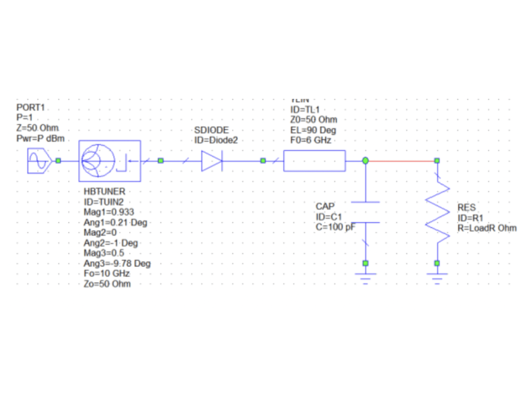
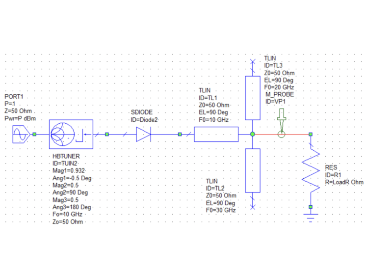
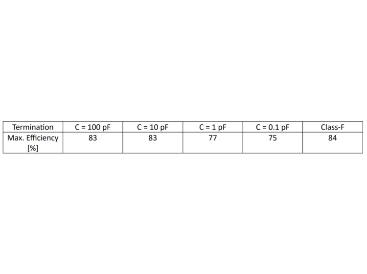
As can be seen from Table V, class F terminations have the potential to increase overall efficiency, even though marginally. However, in this case the exact values of efficiency will be determined by the losses of the capacitive and class-F termination implementation types.
F. Influence of package parasitics
For this purpose, the influence on the designed single diode rectifier was examined for the case when the package parasitics are included in the diode model. For this purpose, an ideal capacitive termination of C = 100 pF was used in both cases. The diode case was assumed to be SOT-23 package [1]. Table VI shows the obtained results. As can be seen, the package does not influence overall efficiency, however, it does influence the maximum power at which the highest efficiency is observed.
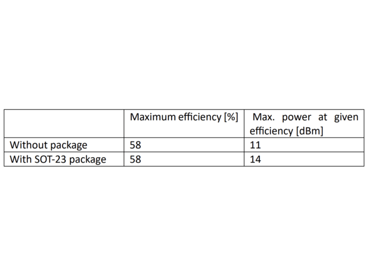
In conclusion, the choice of the active device for the implementation in the circuit of a rectifier is very important as it has a significant impact on overall efficiency, dynamic range, and maximum input powers. As such, choosing the correct diode needs to be taken with great care.
References:
[1] https://en.wikipedia.org/wiki/Small-outline_transistor

Leave a Reply