Functionally, a rectenna is a circuit comprising of an antenna and a rectifying circuit, that can be used to convert Electro-Magnetic (EM) energy into DC. The origins of a rectenna can be traced all the way back to [1], where a rectenna was used to power a helicopter model [2]. The interest in rectennas have soared in recent years, driven by the rise of new ways of energy harvesting. Of note here is the use of Space Solar Power Satellites (SSPS), which collect and convert solar energy into electrical energy, which is beamed down to a ground station on Earth [3]. Here, the efficiency of conversion from EM to DC is of high importance as inefficiencies result in power waste and increased heat. The principle of EM to dc conversion is very simple, as presented in Fig. 1.
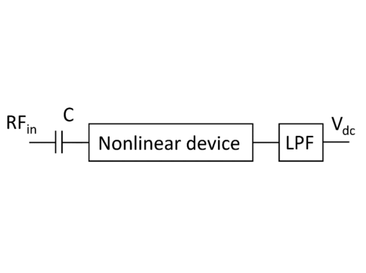
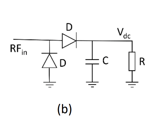
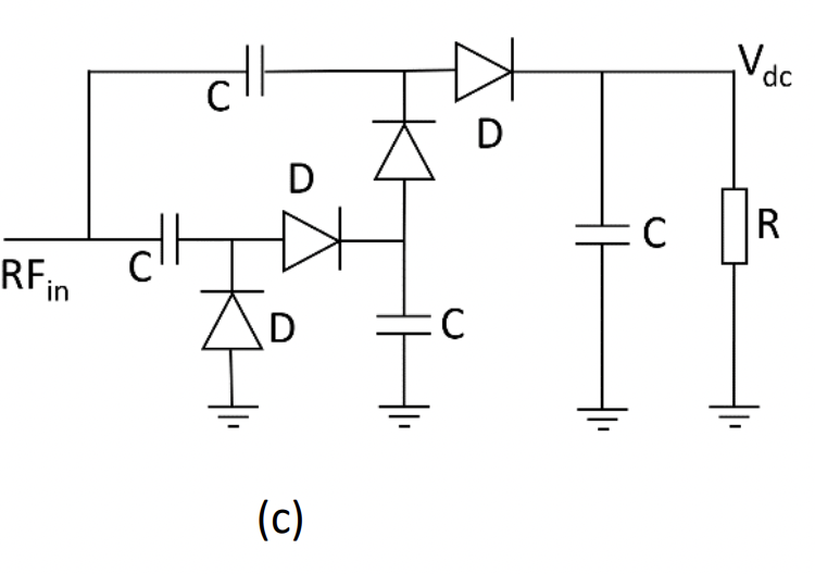
The crux for the correct operation lies with the nonlinear device. The nonlinear device acts as a multiplier, thus creating signals at the output with frequencies at integer multiples of the frequency of the corresponding input signal. If we assume that the frequency of the signal at the input if f1 , the nonlinear device creates signals at frequencies 2f1, 3f1, … and also n*f1 +/- mf1 with n and m being integers. As such, as the output, in addition to the dc signal (f1 -f1) signals at frequencies of f1, 2f1, 3f1…. High frequencies are eliminated by using a Low-Pass Filter (LPF) and its simplest implementation is a capacitor, as shown in simplified, standard rectifying circuits, employing 1, 2 and 4 diodes are shown in Fig. 2. In this figure, the chosen nonlinear device is a diode. The most commonly used diode is a Schottky diode or any other low or zero-barrier diode, in order to increase the efficiency of rectification. The choice between the single, double or 4-diode rectifier is dependent on the maximum input power that the device is expected to handle. Usually, for low power applications a single diode circuit is used, while high power applications usually require rectifiers with a greater number of diodes. However, this has to be carefully evaluated, as diodes with higher breakdown voltage may prove to provide a greater efficiency in a single diode rectifier circuit as compared to rectifiers with a greater number of low breakdown voltage diodes.
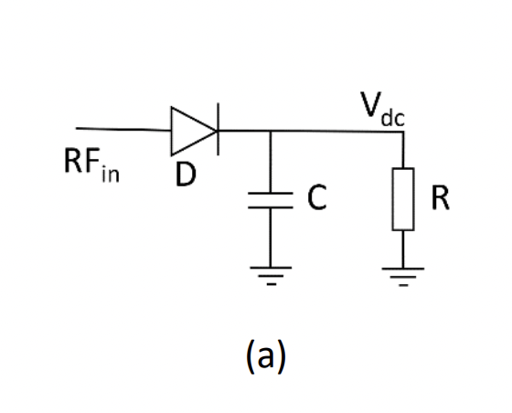
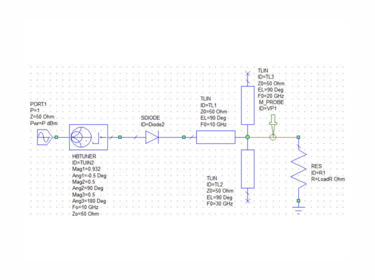
With reference to the single-diode rectifier circuit, we will examine the influence of each diode parameter on the efficiency of the rectifier. For this purpose, we examine the efficiency of a rectifier operating at a frequency of 10 GHz, as a function of: a) influence of threshold and breakdown voltages; b) influence of loss; c) influence of diode’s parasitic resistance; d) influence of diode’s junction capacitance; e) influence of termination type and f) influence of package parasitics. This will be done in Part II, with reference to the circuit of Fig. 2 (a).
References:
[1] US 3434678 Microwave to DC Converter William C. Brown, et al, filed 5 May 1965, granted 25 March 1969
[2]https://en.wikipedia.org/wiki/Rectenna#:~:text=A%20rectenna%20(rectifying%20antenna)%20is,trans mit%20power%20by%20radio%20waves.
[3] N.C. Au, D. M. Nguyen, T. D. Nhu and C. Seo, “A 5.8 GHz rectifier using diode connected MESFET for space solar satellite system”, in IEEE Transactions on Microwave Theory and Techniques, vol. 70, no. 10, October 2022.

Leave a Reply