Monopole antennas are possibly the simplest type of antennas, Fig. 1. Ideally, they consist only of a straight or a tapered rod for bandwidth improvement, which is usually, but not necessarily quarter-wavelength long at the desired frequency of operation. Usually, they are vertically mounted with the lower end of the monopole connected to the signal line, and the remaining end connected to the ground. Effectively, a monopole antenna is an open-ended resonator. The fact that the signal feedline is connected to its lowest point ensures that such excitation results in the broadest possible impedance bandwidth. However, even with this type of excitation, the percentage impedance bandwidth of this antenna is rather small, up to at most 20% [1]. The radiation pattern of this antenna operating at the centre frequency corresponding to quarter-wavelength, is omnidirectional in the azimuthal plane, and its gain drops to zero at the zenith (top of the rod). As the antenna becomes electrically larger (beyond quarter-wave), its radiation characteristic experiences multi-lobes separated through nulls. Understandably, the antenna is linearly polarized, with radiation taking place perpendicular to the antenna.
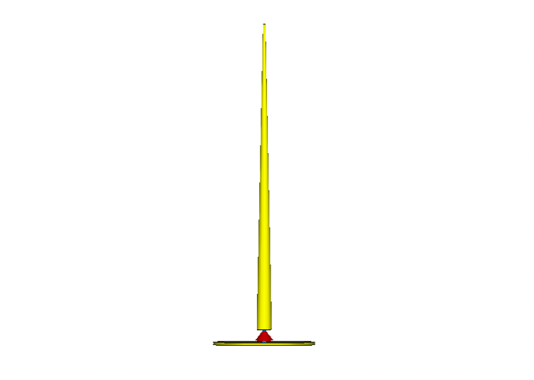
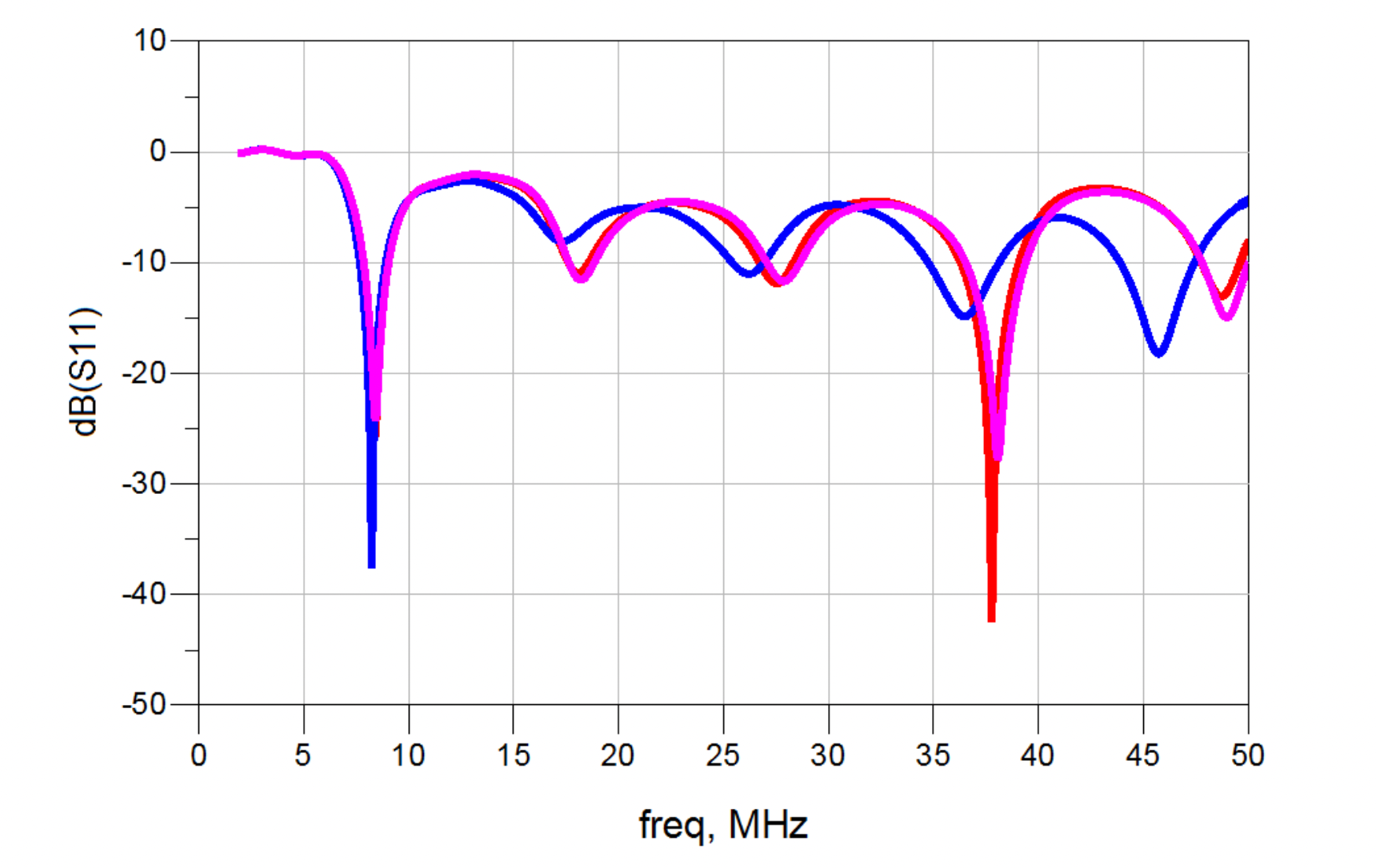
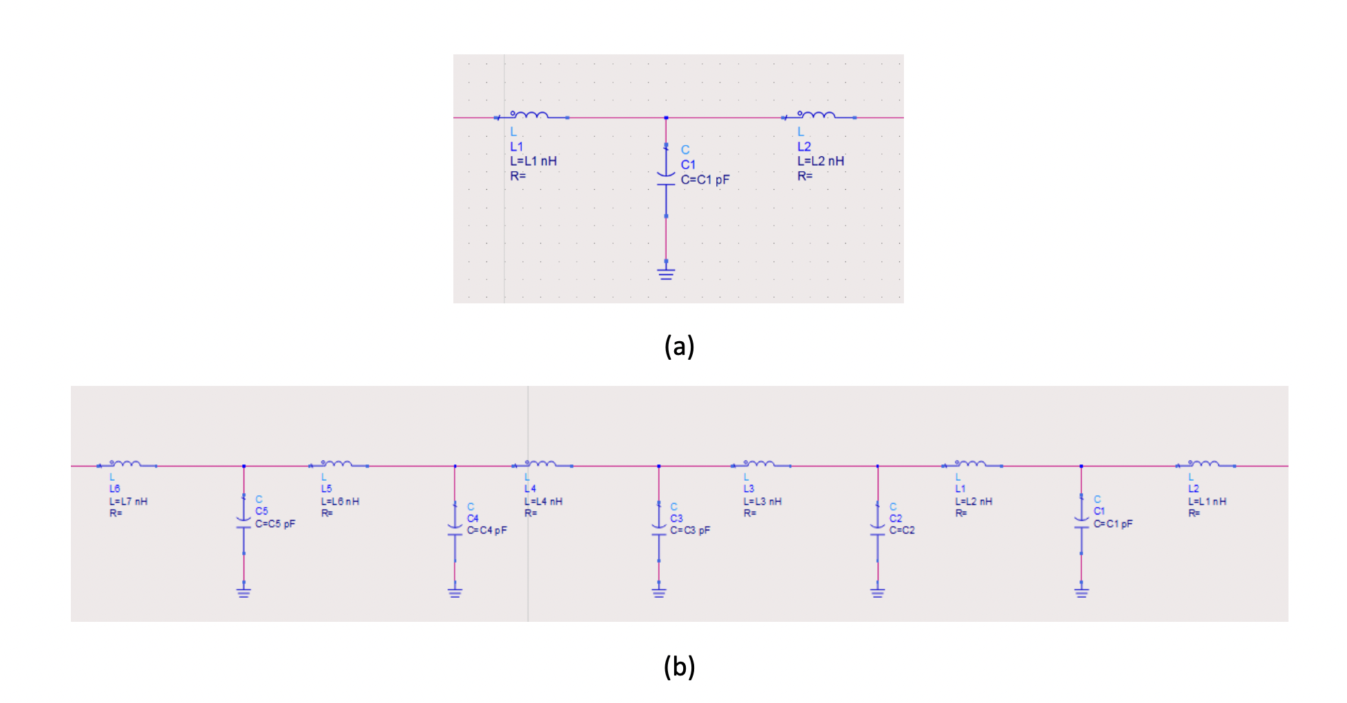
Let us now go through an example of a monopole antenna and examine its pertinent characteristics. Here we will examine the performance of a 12 m monopole antenna with a bottom diameter of 20 cm and top diameter of 5 cm, as depicted in Fig. 1. Fig. 2 depicts the reflection coefficient of this antenna, with and without impedance matching circuits. The antenna has a fundamental frequency of operation at 6.25 MHz, corresponding to its being a quarter-wavelength long at this frequency. The antenna is made of aluminium, with a conductivity of 3.56 x 10⁷ S/m. As can be seen from this figure, the percentage 6-dB-bandwidth of the antenna with no matching network is between 7.4 MHz to 9.6 MHz, corresponding to a percentage bandwidth of approximately 24.3% (red line). Also shown is the response with the antenna having lossless matching circuits. The first matching circuit is standard and contains a lossless “T” network of lumped elements (inductors and capacitors), Fig. 3 (a). This matching network consists of only 3 elements – 2 inductors and 1 capacitor. The addition of the 3rd order lossless matching circuit has only marginally improved the bandwidth of the antenna, with an absolute bandwidth from 7.33 MHz to 9.47 MHz, corresponding to a percentage bandwidth of 25.1% (blue line). Monopole antennas offered on the market in this frequency range and of this size, appear to exhibit a much larger bandwidth, with bandwidths from 2 to 30 MHz [2] considered as standard. One could ask, how could the bandwidth of a monopole antenna be increased this much? Could the addition of a much higher order matching circuit help? The short answer is no. The addition of higher order lossless matching circuits introduces a much more complex and high Q frequency response, which does very little to improve the bandwidth. If anything, the bandwidth only marginally increases. Fig. 2 also depicts the return losses with a monopole antenna matched using an 11th order matching circuit (pink line), which shows very little improvement in terms of the bandwidth compared to the antenna with no matching circuit. It is interesting that a better performance is obtained from the 3rd order lossless matching circuit than with its 11th order equivalent. In conclusion of this part, lossless matching circuits can only marginally increase the bandwidth, inferring that the real reason for bandwidth increase is still on the loose.
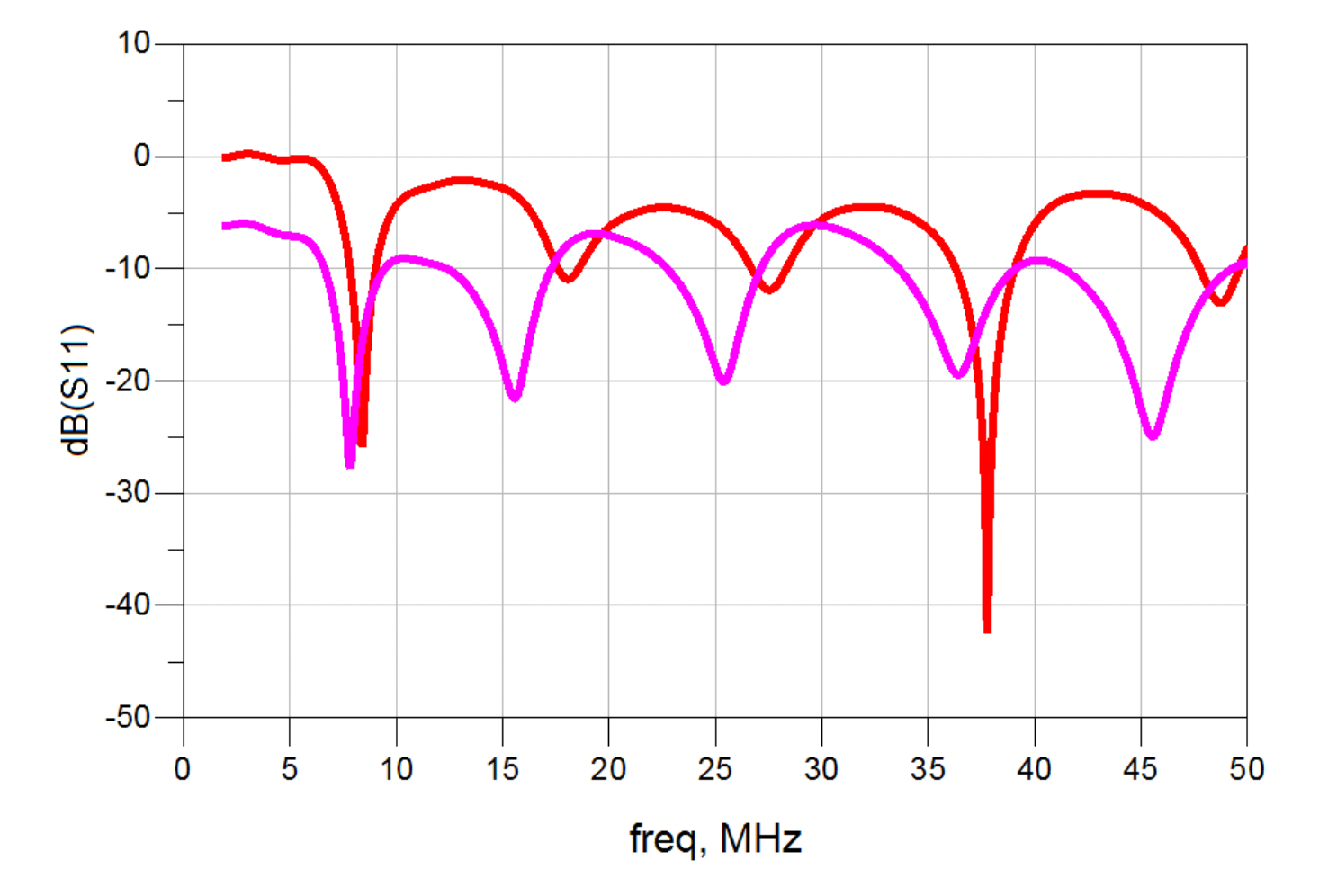
An obvious way to increase the bandwidth is to increase the losses. The losses can be introduced either in the circuit of the antenna as the antenna can be made of a low conductivity material or the losses can be introduced through the matching circuitry. On the one hand, this is usually not a good idea as the radiation efficiency of the antenna significantly reduces. On the other hand, however, the improvement in return losses protects the active part of the RF front end, as no unwanted power is reflected back to the Power Amplifier (PA). Let us now examine the influence of losses on the bandwidth. Fig. 4 (pink line) shows the response of the monopole antenna of Fig. 1, using a lossy 3rd order matching circuit. The losses of the matching circuit are approximately 3 dB. As can be seen, the return loss of the antenna has improved tremendously as the antenna exhibits a standard 6-dB return loss bandwidth from 2 MHz to 50 MHz. One may ask if this level of loss is really introduced into the antennas available on the market? 3-dB loss corresponds to 50% of input power being dissipated in the resistive part of the matching circuit and, as such, not radiated, which is substantial. If this is indeed the case, how is this loss introduced into the antenna? The answer to the first question is yes as real matching circuits (ferrite-based for size reduction) and baluns operating at High Frequencies (HF) already exhibit this level of insertion loss [3]. Once these circuits are deployed in a real-world antenna, the broadband return loss gives one a false illusion that the antenna is operating reasonably well. Let us now check the gain of the monopole antenna in frequency range from 2-50 MHz. This is depicted in Fig. 5.
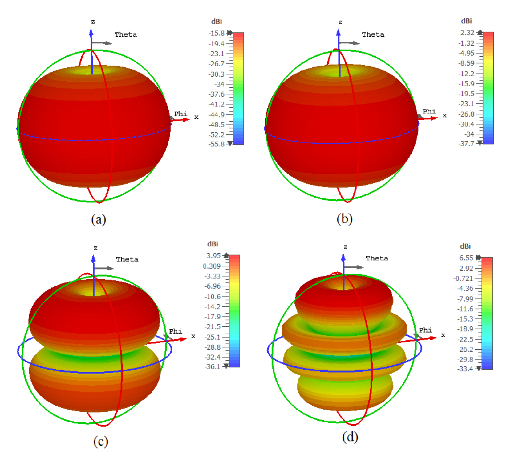
The radiation pattern of the standard monopole antenna operating at the centre frequency corresponding up to quarter-wavelength, is omnidirectional in the azimuthal plane, and its gain drops to zero at the zenith (top of the rod). This is evident from Fig. 5 (b), corresponding to the frequency of 6.25 MHz. The antenna gain at this frequency is 2.32 dBi. As the antenna becomes electrically larger (beyond quarter-wave), its radiation characteristic in the azimuthal plane experiences multi-lobes separated through nulls. This is evident in Fig. 5 (c) and Fig. 5 (d) at frequencies of 25 MHz and 50 MHz. The gain at these frequencies is 3.95 dBi and 6.55 dBi, respectively, which is understandable as the antenna becomes electrically larger as frequency increases. However, of main interest is the antenna radiation performance at its lowest frequency of operation – 2 MHz. Here, even though the shape of radiation characteristics is similar to that at 6.25 MHz, its gain is much lower – 15.8 dBi. We now see the price of using lossy matching networks – the antenna is well impedance matched even at very low frequencies, but its radiated power is just too low to be considered an effective radiator. Usually this is compensated for by the PA being required to deliver higher power at low frequencies.
In conclusion, the broadband operation of monopole antennas available on the market is solely made possible by the introduction of losses. The introduction of losses, even though it increases the bandwidth of operation, only masks the poor behavior of the antenna at low frequencies, where as we have seen, the antenna gain dramatically drops.
References:
[1] Danuor P, Anim K, Jung YB. Monopole Antenna with Enhanced Bandwidth and Stable Radiation Patterns Using Metasurface and Cross-Ground Structure. Sensors (Basel). 2022 Nov 7;22(21):8571. doi: 10.3390/s22218571. PMID: 36366267; PMCID: PMC9657396.
[2] https://antennas.com/wp-content/uploads/2020/08/SB-230-SpecSheet.pdf
[3] https://g8jnj.net/broadbandhfvertical.htm

Leave a Reply