Phase shifters are omnipresent in telecommunications. They play an important role in radar, phased-array and receiver systems. Reflective-type Phase Shifter (RTPS) circuits, with inherently well-impedance matched inputs/outputs are of particular interest for applications where high phase shift values, excellent performance and small size are of importance.
Phase shifters are omnipresent in telecommunications. They are important components for many applications, such as, radar, smart antennas, and measurement systems. Therefore, considerable efforts have been dedicated to the design and characterization of various circuit topologies capable of providing phase variation. Various factors influence phase shifter design. They can be clustered into two relatively loosely independent groups: the first group are circuit-topology related, for example, the amount of obtainable phase shift, insertion loss, bandwidth, etc., whereas the second group are technology related: miniaturization, integration with other components and power handling, to name a few. However, with the advance of technology, the borderline between these two groups has become less pronounced and, therefore, the selection of the phase shifter depends entirely on application requirements. The reflection type phase shifter (RTPS) was mainly intended for use in airborne applications as a replacement for bulky and impractical ferrite phase shifters. However, the use of a single varactor diode as the loading element in the circulator circuit provided a low value of the phase shift (lower than 180o). Technology development led to the replacement of heavy ferrite-based circulators with 3-dB couplers. This resulted in an increase of the number of varactor diodes from 1 to 2 (one diode per reflective load), however, the overall weight of the RTPS formed in this way was significantly reduced. By resonating the varactor diode with an inductor, the amount of phase shift was tremendously increased (up to 180o), however, that came at the cost of bandwidth reduction and increase in insertion losses. Through the integration of two series inductor-resonated varactor diodes connected in parallel, one was able to achieve a 360o. In this configuration each reflective load of a 3-dB coupler is connected to a parallel connection of two series varactor-inductor circuits, yielding the total number of varactor diodes used for a 360o RTPS to 4.
In this article, a new 360o RTPS is presented, which combines the use of a varactor diode and a PIN diode in the circuit of the reflective load. This combination renders the following advantage. The resistance of the varactor device dictates the insertion losses and so, reducing the number of varactors cuts down these losses. Because the PIN diode is used as a switch, it can be replaced by a FET or by a MEMS, where in the latter case integration issues with the rest of the phase shifter circuit need to be resolved. The new phase shifter circuit can be realized in MMICs and RFICs. It also lends itself to a very efficient use of the varactor, as it is capable of providing a complete 360o phase shift even for a very small varactor capacitance ratio, without compromising the losses. Also, if required, the phase shift from this configuration can be extended beyond 360o for any value of the capacitance ratio provided that the limitations imposed by the switching device finite DC resistance are overcome. The analysis and design equations for the loads together with the range of obtainable phase shifts are presented together with a practical circuit realization of a 360o phase shifter operating at a frequency of 2.5 GHz. The results are discussed.


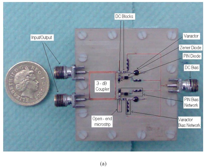
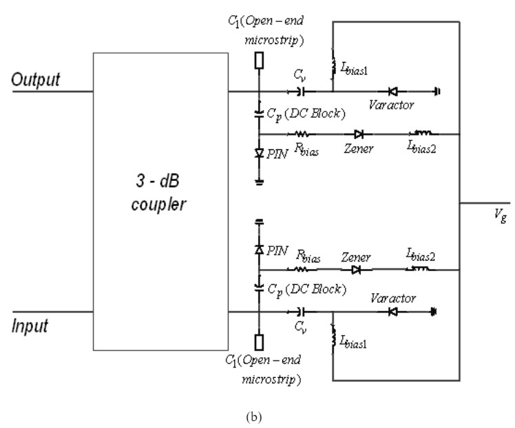
Fig. 1 Practical hybrid varactor-PIN diode phase shifter (a) and its circuit diagram (b)


Leave a Reply