Dr. Senad Bulja, PhD, FIET, SMIEEE

  • Home
  • Researches
  • Workshops
  • Patents
  • Products
  • Tutorials
  • Solutions
  • Services

Workshops

Home » Workshops » 3.5 GHz filter, LTE, band 42

3.5 GHz filter, LTE, band 42

Dr. Senad Bulja 20/12/2023Download Here

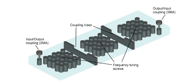
Here, we would like to report on the development of a 3.5 GHz filter operating in band 42 of the LTE frequency band[1]. The filter consists of 8 resonators, each with an unloaded Quality (Q) factor of over 2,800 and has internal dimensions of 40 x 25 x 25 mm3. Figure 1 depicts the internal structure of the resonator. From this figure, the resonator is slightly loaded with a matrix of 5 x 5 resonant elements, necessary to a) reduce the frequency of operation and b) keep the dimensions within the prescribed form factor and c) reduce post-fabrication filter tuning requirements. The specifications of the filter include passband loss of less than 1.25 dB at band edges and at least -15 dB attenuation at 10 MHz offset from the band edges. In addition, the return loss is to be kept at at least -18 dB.

Figure 1: Modelled resonator with a resonant matrix of 5x5 (left) and fabricated resonator (right)
Figure 1: Modelled resonator with a resonant matrix of 5×5 (left) and fabricated resonator (right)

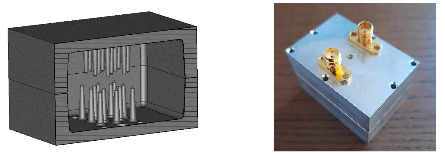
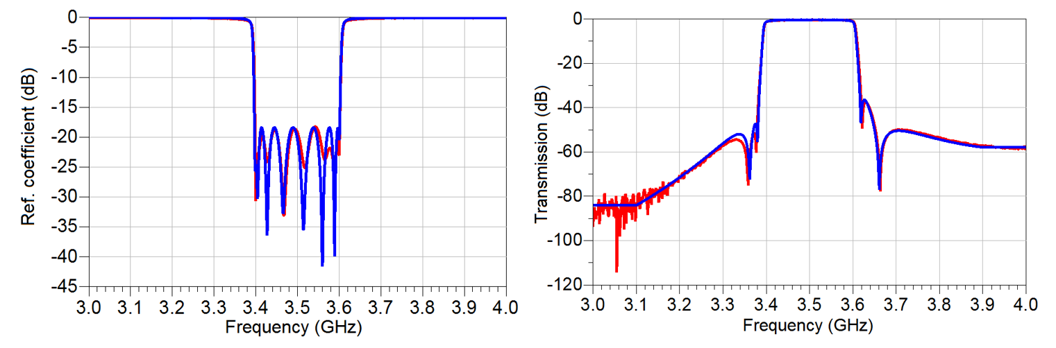
The designed filter is shown in Figure 2. The total internal dimensions of the filter are 110 x 41 x 52 mm3. The filter has 3 cross couplers necessary to introduce 4 transmission zeroes – 2 on the lower skirt and the remaining two on the upper skirt of the response, Figure 3.

Figure 2: Designed 8-pole 3.5 GHz filter (left) and fabricated filter, top view (right)
Figure 3: Simulated (blue) and measured (red) reflection coefficient shown on the left; and simulated (blue) and measured (red) transmission coefficient of filter of Figure 2

Highlights:

  1. The correspondence between the simulated and measured filter responses is excellent.
  2. Both simulated and fabricated filters meet all specifications of band 42, LTE standard.
  3. As an example, the return loss is no less than 18.2 dB and insertion losses are kept well below 1.25 dB at the band edges.
  4. Please contact us for more details.

Chia sẻ0
Tweet
Chia sẻ

Leave a Reply Cancel reply

Your email address will not be published. Required fields are marked *

Other Posts

RF phase shifters

Fig.1 Fabricated circuit prototype of proposed reduced-α DPA

RF amplifiers

RF and mm-wave filters

Profile & Bio

Senad Bulja, Ph.D., FIET, SMIEEE 

  1. Dr Bulja’s profile
  2. Email : contact@drbulja.com

PROFESSIONAL Profile

  • Accomplished career of over 19 years demonstrating consistent success as a Researcher, Leader and Mentor in the Wireless industry research environment.
  • Excellent Scientific contributions in the field of RF, EMC and telecommunications with 4 Nature Journal publications and over 70 peer-reviewed articles and conference papers
  • Strong leadership skills demonstrated by leading Ph.D. level educated cross-continental and cross-departmental teams to successful project execution.  
  • Proven Strategic Business Impact – introduced own developed technology into Nokia’s future technology roadmap (RF filters) and business transfer of the smart surface technology. 
  • Creative, internationally awarded and well-driven inventor with over 70 filed patents in the area of hardware for Radio Frequency (RF), Wireless Sensor Networks (WSN), Internet of Things (IoT) and wireless systems architectures. E.g. Nokia patent award entitled: “A top inventor in implementation patent first filings”, 2020.
  • Significant contribution in the identification of high revenue IP assets and leadership on the creation of Nokia’s patent portfolio roadmap. 
 

© Copyright 2023 drbulja.com. All Rights reserved