
Analogue phase detectors are essential circuits in RF and mm-wave applications when the phase difference between two signals needs to be found. There are many communication scenarios when one needs to know the phase difference between two signals – such as power combining.
Analogue phase detectors are relatively simple microwave circuits; however, it is not popular knowledge how they exactly work. In this article, basics operational principles of phase detectors are presented.
Nonlinear circuits – basic principles
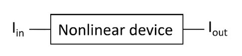
In order to understand how phase detectors work, one needs to know the basic principles of nonlinear circuits, such as diodes and transistors, Fig. 1. In any nonlinear circuit, the signal at the output is not only linearly proportional to the signal at the input, but also its higher order contributions, as shown in (1).
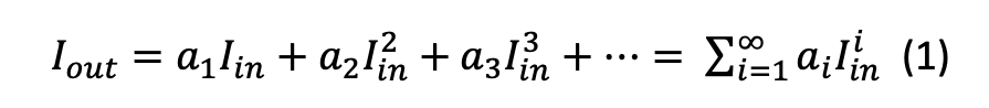
(1) is also known as the Taylor series expansion. In (1), 𝑎𝑖 are the coefficients which are usually experimentally determined. To best describe the output signal, the number of polynomial terms should, in theory, be infinite, but, in practice, only a few terms are used. The number of polynomial terms used in practice depends on the level of nonlinearities exhibited by the device (such as a diode or transistor) and the power of the input signal.
As an illustration, let us assume that the input signal is a simple sinewave given by 𝐼𝑖𝑛 = 𝐼1𝑐𝑜𝑠(𝜔𝑡 + 𝜙1), and that the number of terms in (1) is limited to 3. The output signal 𝐼𝑜𝑢𝑡 becomes:

In other words, the output signal contains not only the frequency of the input signal, but its harmonics too, namely the products of second and third order mixing. The order of harmonic mixing determines the highest frequency of the response, which in this case is 3ω. This basic rule is used in the design of mixers, and, as we will see later in the design of analogue phase detectors too.
Mixers
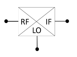
Standard mixers are nonlinear devices and usually have 3 ports – Local Oscillator (LO) port, RF port and Intermediate Frequency (IF) port, as shown in Fig. 2. The signals emanating at the IF port are the signals which are a product of multiplication of the LO and RF signals.
If we assume that the RF signal is given by 𝐼𝑅𝐹 = 𝐼𝑅𝐹_𝑀𝐴𝐺𝑐𝑜𝑠(𝜔𝑡 + 𝜙𝑅𝐹) and LO signal by 𝐼𝐿𝑂 = 𝐼𝐿𝑂_𝑀𝐴𝐺𝑐𝑜𝑠(𝜔𝑡 + 𝜙𝐿𝑂) , the multiplication function of the mixers of Fig. 2 produces the following output:
Where 𝑎2 is the conversion coefficient, usually provided in the datasheet of a mixer and is, as mentioned earlier, experimentally determined. Index I in (3) refers to the fact that both the RF and LO signals are cosine functions or “in-line”. The composite signal given by (3) contains products of second order mixing, which in the present case are DC and the second harmonic. The first term in (2), the DC term, is of particular use in the design of phase detectors, as will be explained later.
Phase detectors using mixers
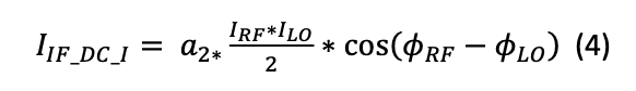
The DC term in (3) is proportional to the phase difference between the LO and RF signals and, can, in theory, be used to construct a phase detector. However, the main issue lies with fact that the extracted phase in that case would be dependent on the correct extraction of the “amplitude” of the DC “signal”, i.e., 𝑎2 ∗(𝐼𝑅𝐹∗𝐼𝐿𝑂)/2. Theoretically, this could be considered through a careful calibration of the mixer, but that would make the phase detector constructed in this way highly dependent on the power levels applied to RF and LO ports, which increases its sensitivity. It should be noted that the second harmonic in (2) can be easily eliminated using a low-pass filter. In many instances, a grounded capacitor should suffice. By eliminating the second harmonic, the DC IF output of (3) now becomes:
To eliminate phase difference dependence on LO and RF power levels, one more piece of information is required. For this purpose, let us now assume that the LO signal is phase shifted by 𝜋/2. The LO signal now becomes:

Index Q in (5) refers to the fact that the RF and LO signals are “in quadrature”, i.e., the LO signal is a sine function, while the RF signal is a cosine function. Mixing such an LO signal with an RF signal given by 𝐼𝑅𝐹 = 𝐼𝑅𝐹_𝑀𝐴𝐺 𝑐𝑜𝑠(𝜔𝑡 + 𝜙𝑅𝐹 ) produces the following IF output:

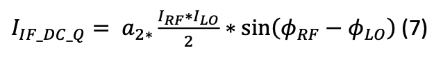
The DC part of (6) is now equal to:
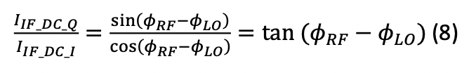
The ratio of (7) over (4) now gives:
From which the phase difference can be extracted in a simple manner by:
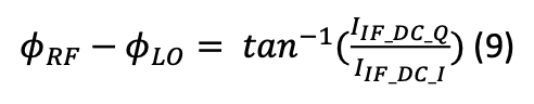
As obvious from (9), the measured phase difference is no longer a function of input powers of the LO and RF signals. The circuit that performs this function is given in Fig. 3.
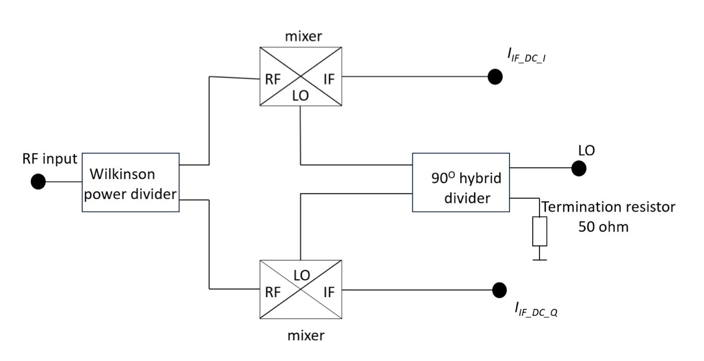
As such, in theory, a phase detector can be constructed using two mixers and passive RF circuitry. In practice, care must be taken so that appropriate power levels are applied to the LO and RF ports; here, usually the power applied to the RF port needs to be at least 10 dB lower compared to the power applied to the LO port, for the mixers not to exceed their maximum power ratings [1]. In addition, IF ports need not be terminated in 50 Ω; the IF outputs in the present configuration are behaving as current sources and higher termination resistances are usually recommended, but that is design dependent.
Conclusions
In this short article, basic principles of operation of nonlinear circuits are presented, together with their use in the design of mixers and phase detectors. Both mixers and phase detectors are important RF/mm-wave devices used in a variety of telecommunications systems.
References:
[1] https://www.minicircuits.com/pages/pdfs/mixer1-2.pdf
[2] https://www.minicircuits.com/app/AN00-011.pdf

Leave a Reply